昨年末から国内外で出願公開されているマツダのEV専用スケーラブルアーキテクチャー関連と思われる特許ですが、米国で新たな関連特許が公開されました。
マツダは2021年6月に「SKYACTIV EV専用スケーラブルアーキテクチャー」の開発を公表しましたが、このアーキテクチャーに関係すると思われる特許出願が昨年末頃から国内外で公開。
(一例)
ラダーフレームのようにボディとシャシーを上下分離可能になっている事に加えて、以前から度々特許が出願されているアルミ製スペースフレームとの関連性も伺える内容になっていましたが、今週米国で新たな関連特許が公開されています。
〇米国特許商標庁(USPTO)
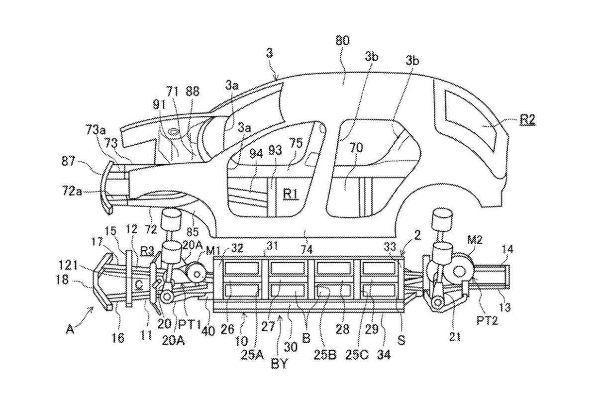
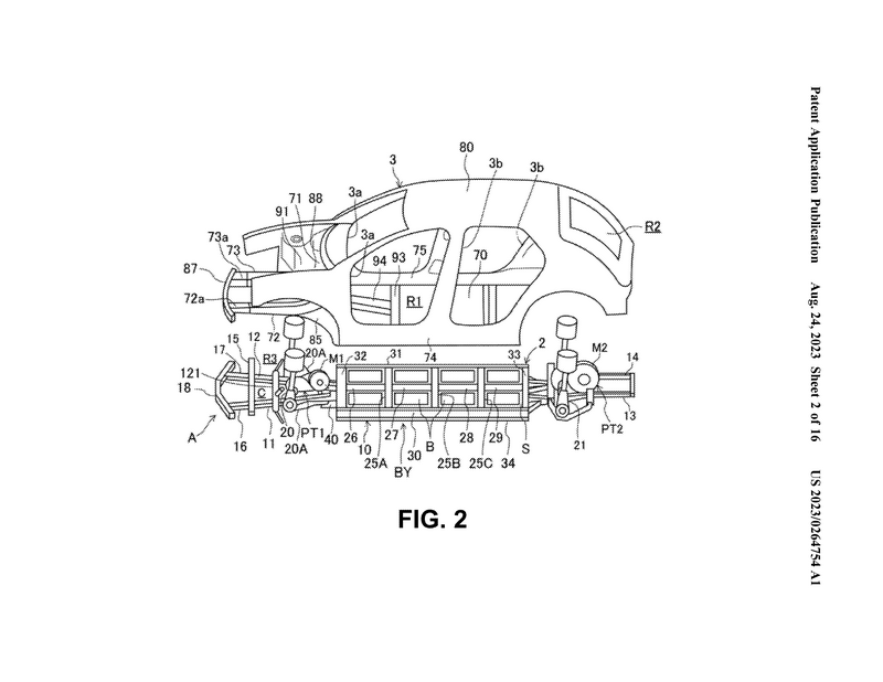
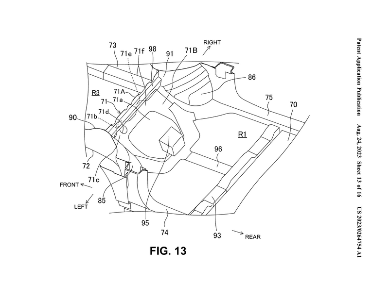
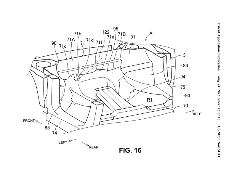
①「VEHICLE-BODY FRONT STRUCTURE(車体前部構造)」
(出願番号:US 20230264754 A1)
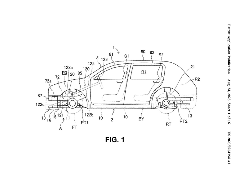
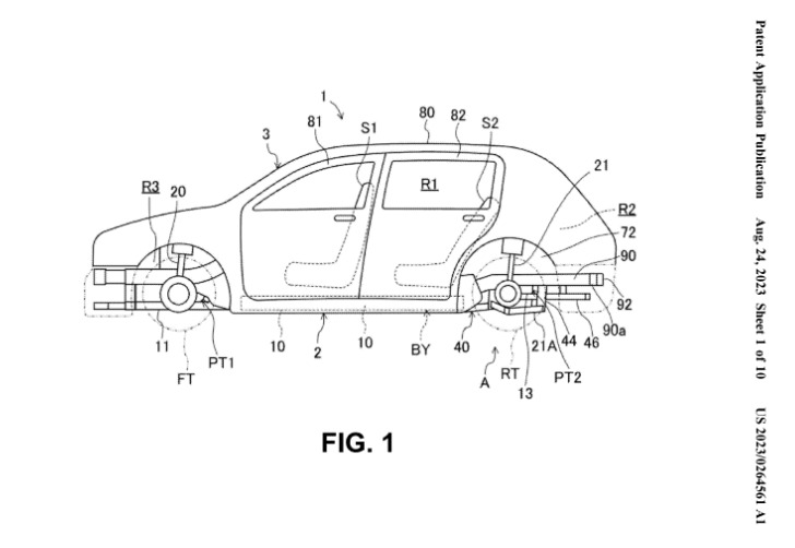
As illustrated in FIG. 1, the electric vehicle 1 is a passenger automobile. The electric vehicle 1 may be of any of a sedan type, a hatch-back type, a minivan type, and so forth, and its shape is not particularly limited.
図1に示した電気自動車1は乗用車である。電気自動車1は、セダンタイプ、ハッチバックタイプ、ミニバンタイプ等のいずれであってもよく、その形状は特に限定されない。
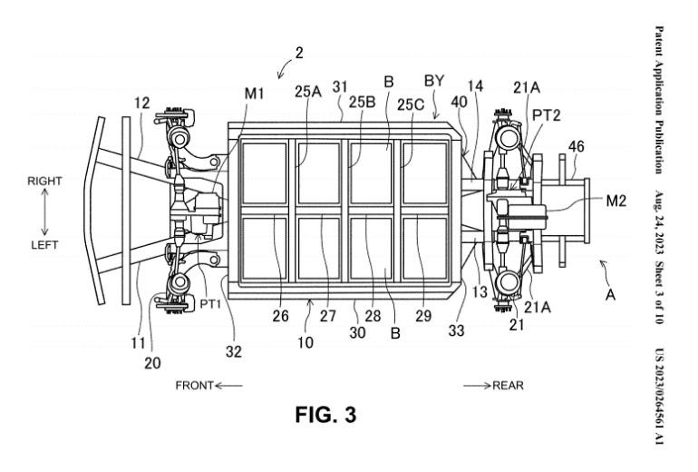
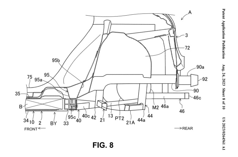
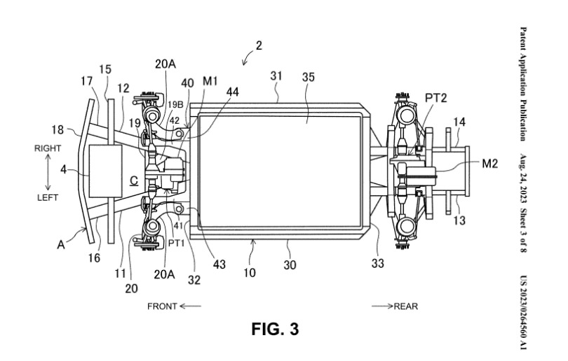
In the present embodiment, the rear-side traveling motor M2 is configured to produce a highest output (maximum torque) which is high compared to the front-side traveling motor M1, and the rear-side traveling motor M2 has a larger size than the front-side traveling motor M1.
Accompanying that, the rear-side power train PT2 becomes larger than the front-side power train PT1.
本実施形態では、リアモーターM2は、フロントモータM1に比べて最高出力(最大トルク)が大きくなるように構成されており、リアモーターM2はフロントモータM1よりも大型である。
これに伴い、リア側パワートレインPT2がフロント側パワートレインPT1よりも大型化する。
Note that the rear-side traveling motor M2 may produce a highest output which is low compared to the front-side traveling motor M1, or the rear-side traveling motor M2 and the front-side traveling motor M1 may produce equivalent highest outputs.
なお、リアモーターM2は、フロントモーターM1に比べて低い最高出力としてもよいし、リアモーターM2とフロントモーターM1の最高出力を同じにしてもよい。
Further, only the front-side power train PT1 may be provided, or only the rear-side power train PT2 may be provided. Further, for example, in a case of a large-sized vehicle, the front-side traveling motor M1 and the rear-side traveling motor M2 are installed which are large compared to a small-sized vehicle.
また、フロント側パワートレインPT1のみを設けてもよいし(=前輪駆動)、リア側パワートレインPT2のみを設けてもよい(=後輪駆動) また、例えば大型車両の場合は小型車両に比べて大型のフロントモーターおよびリアモーターM2が搭載される。


The lower structure 2 includes the front and rear power trains PT1 and PT2, the front wheels FT, the rear wheels RT, front suspension apparatuses 20, rear suspension apparatuses 21, and so forth in addition to the battery casing 10, the front side frames 11 and 12, and the rear frames 13 and 14. Forms of the front suspension apparatus 20 and the rear suspension apparatus 21 are not particularly specified.
下部構造2は、バッテリケース10、フロントサイドフレームの他、前後パワートレインPT1、PT2、前輪FT、後輪RT、フロントサスペンション装置20、リアサスペンション装置21等を含む。 フロントサスペンション20およびリアサスペンション21の形式は特に限定されない。
〇資料に記載されている特許の目的
The present disclosure has been made in consideration of such problems, and an object thereof is, in an electric vehicle, to satisfy both of a requirement for absorption of an impact load in a collision and a requirement for layout of the direction and position of the steering wheel.
本発明の目的は、電動車両において衝突時の衝撃荷重の吸収要求とステアリングホイールの向き及び位置のレイアウト要求を両立させることにある。
②「REAR VEHICLE-BODY STRUCTURE(後部車体構造)」
(出願番号:US 20230264561 A1)


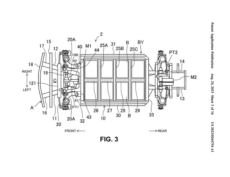
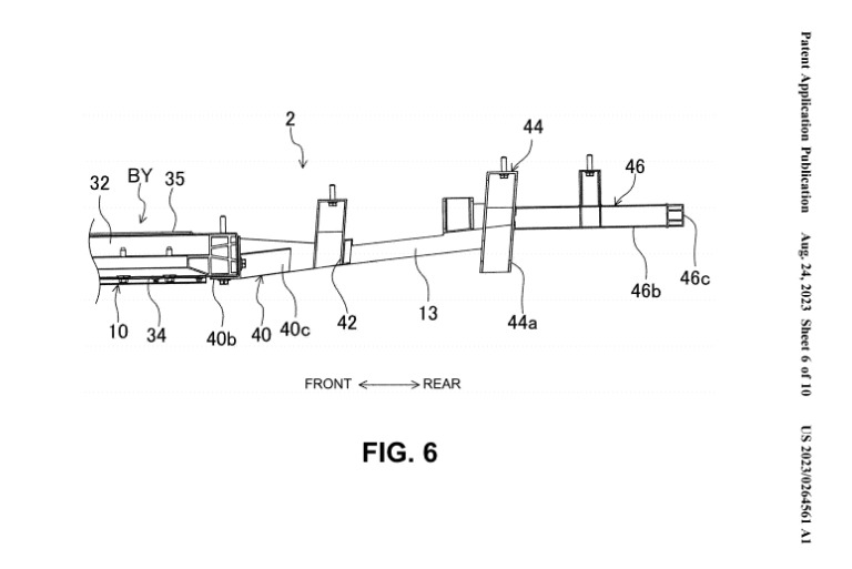
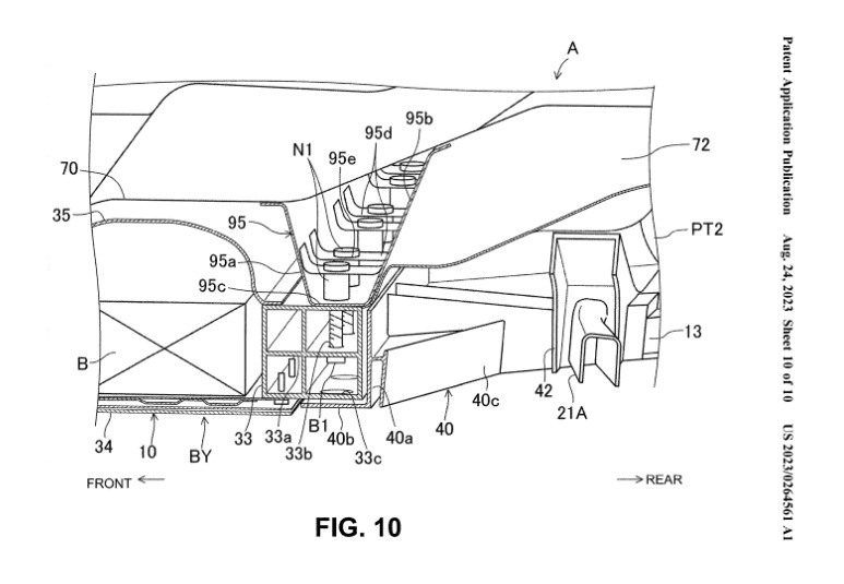
The size of the battery housing space S can be changed in accordance with the capacity of the installed batteries B. The size of the battery housing space S is capable of being easily changed by changing lengths of the left-side battery frame 30, the right-side battery frame 31, the front-side battery frame 32, and the rear-side battery frame 33 and a shape of the bottom plate 34.
バッテリ収容空間Sの大きさは、搭載するバッテリBの容量に応じて変更することができる。バッテリ収容空間Sの大きさは、左側バッテリフレーム30・右側バッテリフレーム31の長さと、前側バッテリフレーム32、後側バッテリフレーム33の形状と底板34の形状をを変えることで容易に変更することができる。
In a case where the left-side battery frame 30, the right-side battery frame 31, the front-side battery frame 32, and the rear-side battery frame 33 are configured with the extruded material, the lengths can easily be changed. Further, the bottom plate 34 can also be configured with the extruded material, and its shape can thereby easily be changed.
左側バッテリフレーム30、右側バッテリフレーム31、前側バッテリフレーム32および後側バッテリフレーム33を押出材で構成する事で長さを容易に変更することができる。 また、底板34も押し出し材で構成することで形状を容易に変更することができる。

〇資料に記載されている特許の目的
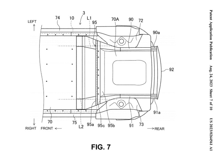
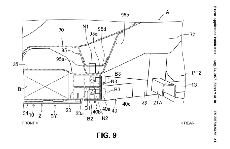
The present disclosure has been made in consideration of such problems, and one of the objects thereof is to enable an impact load from vehicle rear to be absorbed even in a case where an installation space of batteries is elongated to a vehicle rear side and an installed amount of the batteries is increased.
本発明はバッテリー搭載スペースが車両後方側に長く、バッテリー搭載量が増えた場合であっても、車両後方からの衝撃荷重を吸収できるようにすることを目的とする。
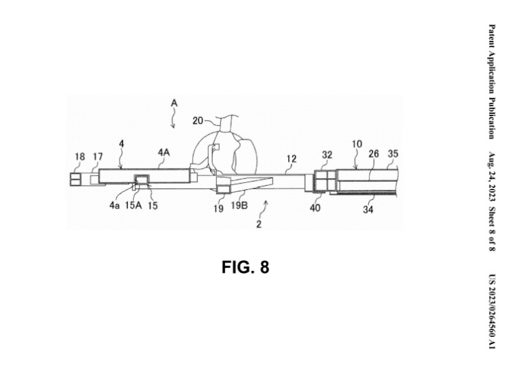
③「VEHICLE-BODY FRONT STRUCTURE INCLUDING A CONTACTLESS CHARGER(非接触充電器を装着した車体前部構造)」
(出願番号:US 20230264560 A1)
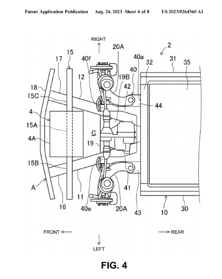

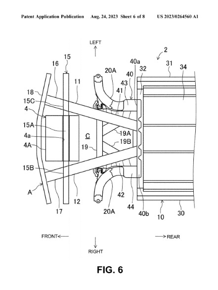
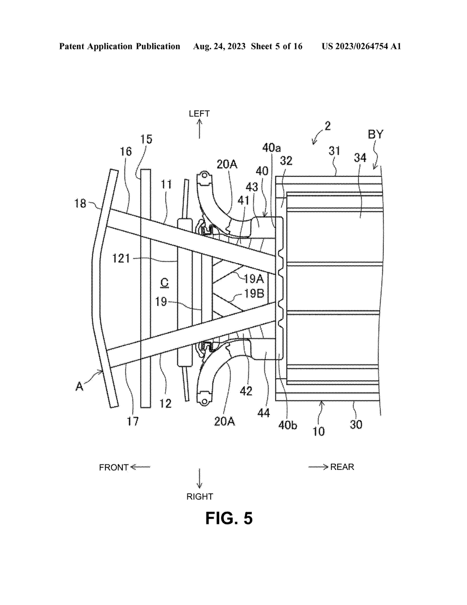
In the present embodiment, the contactless charger 4 is arranged in the space C formed between the left and right front side frames 11 and 12. The contactless charger 4 is configured to be capable of receiving a charging current for the batteries B, e.g., from the outside.
本実施形態では、非接触充電器4は左右のフロントサイドフレーム11,12の間に形成された空間Cに配置されている。非接触充電器4は、例えば外部からバッテリBの充電電流を受電可能に構成されている。
Specifically, the electric vehicle 1 conforms to a system which wirelessly transmits electric power by using electromagnetic induction (wireless power transmission system).
具体的には、電気自動車1は電磁誘導を利用して電力を無線送信するシステム(ワイヤレス電力伝送システム)に適合している。
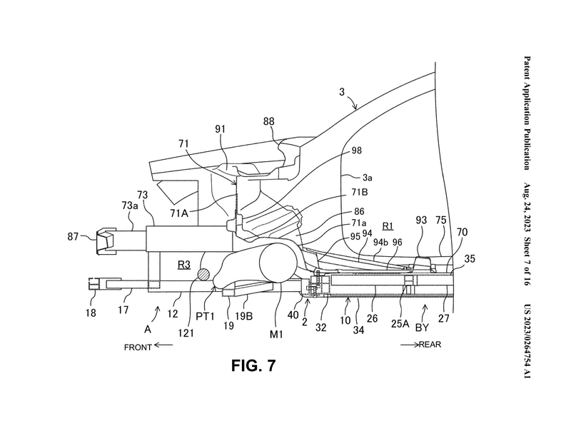
The wireless power transmission system may include a power transmission coil placed directly below the electric vehicle 1 which stands still and the contactless charger 4 of a vehicle-mounted type. The power transmission coil may be placed in a ground surface of a parking lot, a floor surface of a garage, or the like, for example.
ワイヤレス電力伝送システムは、静止する電気自動車1の直下に配置された送電コイルと、車載型の非接触充電器4とを含んでいてもよい。
送電コイルは、例えば、駐車場の地表面や車庫の床面等に配置することができる。

〇資料に記載されている特許の目的
The present disclosure has been made in consideration of such problems, and one or more embodiments is directed to improving layout characteristics of a contactless charger while sufficiently securing impact absorbability in an offset collision.
本発明はオフセット衝突時の衝撃吸収性を十分に確保しつつ、非接触充電器のレイアウト性を向上させることを目的とする。
今回公開されたEV専用アーキテクチャー関連と思われるマツダの特許出願は以上となります。
基本的な構造は先に公開されていた特許出願と同様にラダーフレームのようにボディとシャシーが分離可能になっていますが、説明図に描かれているボディがハッチバックになっているのが特徴(これまではセダンボディ)
マツダはEV専用アーキテクチャーが様々なボディタイプに対応可能である事をすでに公表していますが、特許資料内でも様々なボディタイプの可能性を示唆しているのでしょうか・・・?

そして、今回公開された関連特許で特に注目なのが3つ目に紹介している「非接触充電器(ワイヤレス充電器)」
これまで見た限りだとマツダの特許関連情報で非接触充電器が登場したのは今回が初めてです。
非接触充電器はまだグローバルで実証実験が始まった段階ですが、今後国や地域によって充電方法が異なる可能性もあるので、マツダとしても様々な可能性を視野に入れて開発してるのでしょうね・・・。
(トヨタ公式HP)
今回の特許出願3件は米国で公開された内容を自動翻訳ベースで取り上げたので一部フォローし切れてない部分もあるかと思いますが、今後日本でも出願情報が公開される可能性が十分考えられるので、公開されたら改めてチェックしたいと思います。