
2025年以降に導入予定と公表されているマツダの「EV専用スケーラブルアーキテクチャー」ですが、これに関係すると思われる特許が米国で複数出願されていました。
マツダは2021年6月にEV専用のプラットフォーム「SKYACTIV EV専用スケーラブルアーキテクチャー」を発表し、2022年11月には使用した場合の一例も公開。
欧州マツダの関係者からは実用車だけでなくスポーツカーも視野に入れる事が出来るくらいの拡張性が備わるという証言も出てきています。


2025年~2030年にかけて導入予定と公表されていますが、EV専用スケーラブルアーキテクチャーに関係すると思われる特許が昨年末に続いて公開されました。
まずは昨年末に公開された関連特許を簡単におさらい。
〇昨年末に公開された特許出願を取り上げた記事。


ラダーフレームのように車体上部と下部をボルトやネジで締結して上下分離可能になっている事が大きなポイントですが、説明図や文章を見るとセダンなど車高が低い車種も視野に入れているのも特徴。
今回はこれと関連性が強いと思われる特許が米国で出願されています。
〇米国特許商標庁(USPTO)
USPTOのデータベースを見ると2023年3月30日付でEV専用スケーラブルアーキテクチャー関連と思われるマツダの特許出願が10件以上公開。
説明図は基本的に共通なので、その中からいくつかピックアップして紹介していきます。
(US 20230094186 A1)


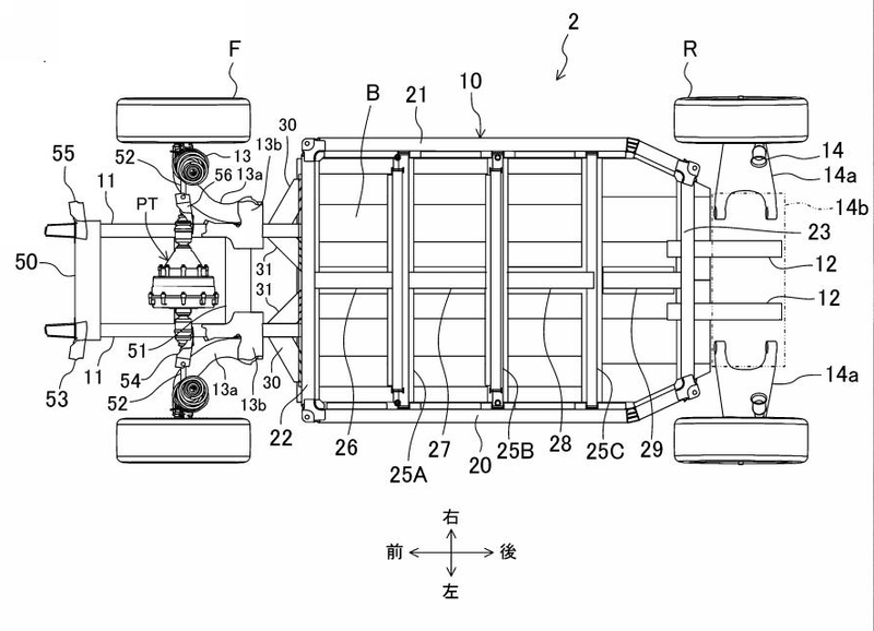
The type of the automobile 1 does not necessarily need to be a four-door vehicle as exemplarily illustrated in FIG. 1 and may be, for example, an automobile including no rear doors RD. Although not illustrated, the present invention is also applicable to an automobile, such as a hatchback vehicle, in which the rear-side space R4 can be opened and closed by a tail gate.
自動車1の種類は、必ずしも図1に例示したような4ドア車である必要はない。 例えば、後部ドアRDを備えていない自動車であってもよい。 また、図示はしないが、ハッチバック車等のテールゲートにより後側空間R4を開閉可能な自動車にも本発明を適用することができる。
Each powertrain PT includes at least a traveling motor M (illustrated in FIG. 2) for driving a drive wheel and also includes a speed reducer, a transmission, or the like as necessary. Thus, the automobile 1 is an electric vehicle. The traveling motor M is disposed such that the rotation center thereof extends in the right-left direction. The powertrain PT may include, for example, a controller in addition to the traveling motor M. The powertrain PT may include an internal combustion engine. A battery unit Y (also illustrated in FIG. 1) for supplying electric power to the traveling motor M is mounted at a lower portion of the automobile 1. For example, the battery unit Y may be charged by using power generated by the internal combustion engine, and either the front wheels FT or the rear wheels RT or both may be driven by power generated by the internal combustion engine.
各パワートレーンPTは、駆動輪を駆動する走行用モータM(FIG2の赤丸部分)を少なくとも含み、必要に応じて減速機や変速機等を含む。 したがって、自動車1は電気自動車である。 走行モータMは、その回転中心が左右方向に延びるように配置されている。 パワートレインPTは、走行用モータMに加えて、例えばコントローラを含んでもよい。パワートレインPTは、内燃機関を含んでもよい。
自動車1の下部には、走行用モータMに電力を供給するバッテリユニットY(図1にも図示)が搭載されている。
例えば、内燃機関の発電電力を用いてバッテリユニットYを充電し、内燃機関の発電電力により前輪FTまたは後輪RTのいずれかまたは両方を駆動してもよい。


In the present embodiment, since each powertrain PT includes the traveling motor M, no internal combustion engine needs to be mounted in the front-side space R2 and thus no exhaust pipe needs to be guided to the vehicle rear side. When a powertrain PT is mounted in the rear-side space R4, the rear wheels RT can be driven by the powertrain PT and a propeller shaft can be omitted. Accordingly, the occupant-space-side floor panel 41 can have a tunnel-less structure.
各パワートレインPTが走行用モータMを備えているので、前側空間R2に内燃機関を搭載する必要がなく、排気管を車両後側に導く必要がない。
後側空間R4にパワートレインPTを搭載すれば、後輪RTをパワートレインPTで駆動することができ、プロペラシャフトを省略することができる。
これにより、乗員室側フロアパネル41をトンネルレス構造とすることができる。
Since the right and left front-wheel suspension support members 51A and 51B are each connected to the front portion of the center frame 80, the stiffness of the front-wheel suspension support members 51A and 51B is increased, which improves maneuvering stability of the vehicle. In addition, the stiffness of the vehicle front side including the vicinity of the dash panel 50 is increased as well.
センターフレーム80(車体中央を前後に貫いているフレーム)の前部に左右の前輪サスペンション支持部材51A,51Bがそれぞれ連結されているので、前輪サスペンション支持部材51A,51Bの剛性が高くなり、車両の操縦安定性が向上する。 また、ダッシュパネル50付近を含む車両前側の剛性も向上する。


The center frame 80 is disposed to be higher than and away from the occupant-space-side floor panel 41 at a right-left direction central portion of the occupant space R1 and extends in the front-rear direction. The distance between a lower surface of the center frame 80 and the upper surface of the occupant-space-side floor panel 41 may be set to be, for example, equal to or larger than 10 cm or equal to or larger than 20 cm at a part separated most.
Since the center frame 80 is arranged to be higher than and away from the occupant-space-side floor panel 41, components and the like can be disposed in a space between a lower surface of the center frame 80 and the upper surface of the occupant-space-side floor panel 41.
センターフレーム80は、乗員空間R1の左右方向中央部において、乗員空間側フロアパネル41よりも高く離間して配置され、前後方向に延びている。センターフレーム80の下面と乗員空間側フロアパネル41の上面との間の距離は、例えば、最も離れた部分で10cmと同等以上、20cmと同等以上となるように設定される。
センターフレーム80は、乗員空間側フロアパネル41よりも高く、乗員空間側フロアパネル41から離れるように配置されているので、センターフレーム80の下面と乗員空間側フロアパネル41の上面の間の空間に部品等を配置することができる。


Since the center frame 80 extends in the front-rear direction, the air-conditioned air can be guided to a desired place in the front-rear direction in the occupant space R1. In this case, since the air introducing duct 122d is arranged at a higher position than the control device 130 and has a predetermined width in the right-left direction, direct sunlight is interrupted by the air introducing duct 122d as well and further unlikely to reach the control device 130. Moreover, since the center frame 80 is used as an air conditioning duct, an air conditioning duct does not need to be redundantly provided and the occupant space R1 can be enlarged as compared to a case in which an air conditioning duct is redundantly provided.
Since the center frame 80 has a cross-section that is large enough to improve the distortion stiffness of the vehicle body, air sending noise can be maintained low when the amount of the air-conditioned air circulating inside the center frame 80 is increased.
センターフレーム80は前後方向に延びているので、エアコンの送風を乗員空間R1の前後方向の所望の場所に導くことができる。 この場合、空気導入ダクト122dは、制御装置130よりも高い位置に配置され、左右方向に所定の幅を有しているため、直射日光は空気導入ダクト122dによっても遮られ、さらに届きにくい。 また、センターフレーム80を空調ダクトとして利用するので、空調ダクトを重複して設ける必要がなく、空調ダクトを設ける場合に比べて乗員スペースR1を大きくすることができる。
センターフレーム80は、車体の歪み剛性を向上させるのに十分な大きさの断面を有するので、センターフレーム80内を循環するエアコンの送風量を増加させても、送風音を低く維持することができる。
(US 20230101421 A1)


(US 20230094186 A1)


基本的な構成は昨年末に公開された時と同様に車体を上下分離可能でモーターの取り付け位置によって駆動方式を自由に変える事が出来るようになっていますが、まず特徴的なのは車体中央を前後に貫いてる「センターフレーム」
今回の特許では車体剛性UPだけでなくエアコンの送風に生かすことまで検討されているようです。
さらに今回公開された特許出願ではセンターフレームの形状が2種類出てきていますが、これはバッテリー容量や車体形状が異なる事を意味してるのかもしれません。
そして何より気になるのは2019年頃から定期的に特許が出願公開されている「スポーツカー用と思われるアルミ製スペースフレーム」の構造と似ている事。
(一例)


フレーム構造がかなり似ている事に加えて、今回の特許でも"アルミダイキャスト"や"アルミ押しだし材"というフレーズが多く出ていた事から共通性はかなり高い予感・・・。
しかし、その一方でモーターだけでなく発電用の内燃機関を搭載する可能性も挙げているにも関わらず、車体フロアは排気管やプロペラシャフトを通す事を考慮していないトンネルレス構造を前提としているのは話が矛盾してしまうので気になるところ・・・。
ただ、一つ可能性を挙げるとマツダはアルミ製スペースフレームに関する特許で一般的な車体中心ではなく"車体右側へ迂回している排気経路"に関する内容を出願しているので、EV専用アーキテクチャーに発電用の内燃機関を搭載した場合でも同じ構造を検討してる可能性も考えられます。


・赤色・・・エンジン
・No.31・・・GPF(ガソリンパティキュレートフィルタ)
・No.32・・・第1プリサイレンサー
・No.33・・・第2プリサイレンサー
・水色・・・メインサイレンサー
さらに、アルミ製スペースフレームは駆動用ロータリーエンジンに関する特許とも関連性が強いので、これらの共通点を見るとマツダが次世代ロータリースポーツとEVアーキテクチャーを"一括企画"しているのでは?という妄想も膨らみますが・・・(笑)
マツダが発電用としてロータリーエンジンを復活させたのもMX-30 R-EV(スモール群)だけでなくEV専用アーキテクチャーにも搭載するのが理由だったりするかもしれませんね。
今回取り上げた特許出願は米国で公開された内容を出来る限り自動翻訳で取り上げた状況なので一部間違ってる可能性もありますが、2025年以降に投入されるEV専用スケーラブルアーキテクチャーにはかなり多くの秘策が込められてるのかもしれません。
今回の特許出願は今後日本でも公開されると思うので、その時は再度詳しくチェックしてみたいと思います。